Creating Clear Solution Architecture Diagrams: Standardizing Optimizely Solutions with the C4 Model and Archimate


TEST
People say that "Drawing great solution architecture diagrams is an art”. Drawing solution architecture diagrams does involve a lot of creativity: Choosing shapes and symbols, colors, and types of arrows, deciding on what to write and where to place all the boxes and so on. But what often happens when people choose their own ways of drawing diagrams is that the architecture is easily misunderstood.
When diagrams fail to present the solution
We have probably all seen diagrams similar to the ones below – all with different design language.
The first one uses colors, lots of symbols, text, logotypes, and dividers - but no connectors/arrows. The described system is in the middle, but its purpose is not clear.
Source: Wikimedia
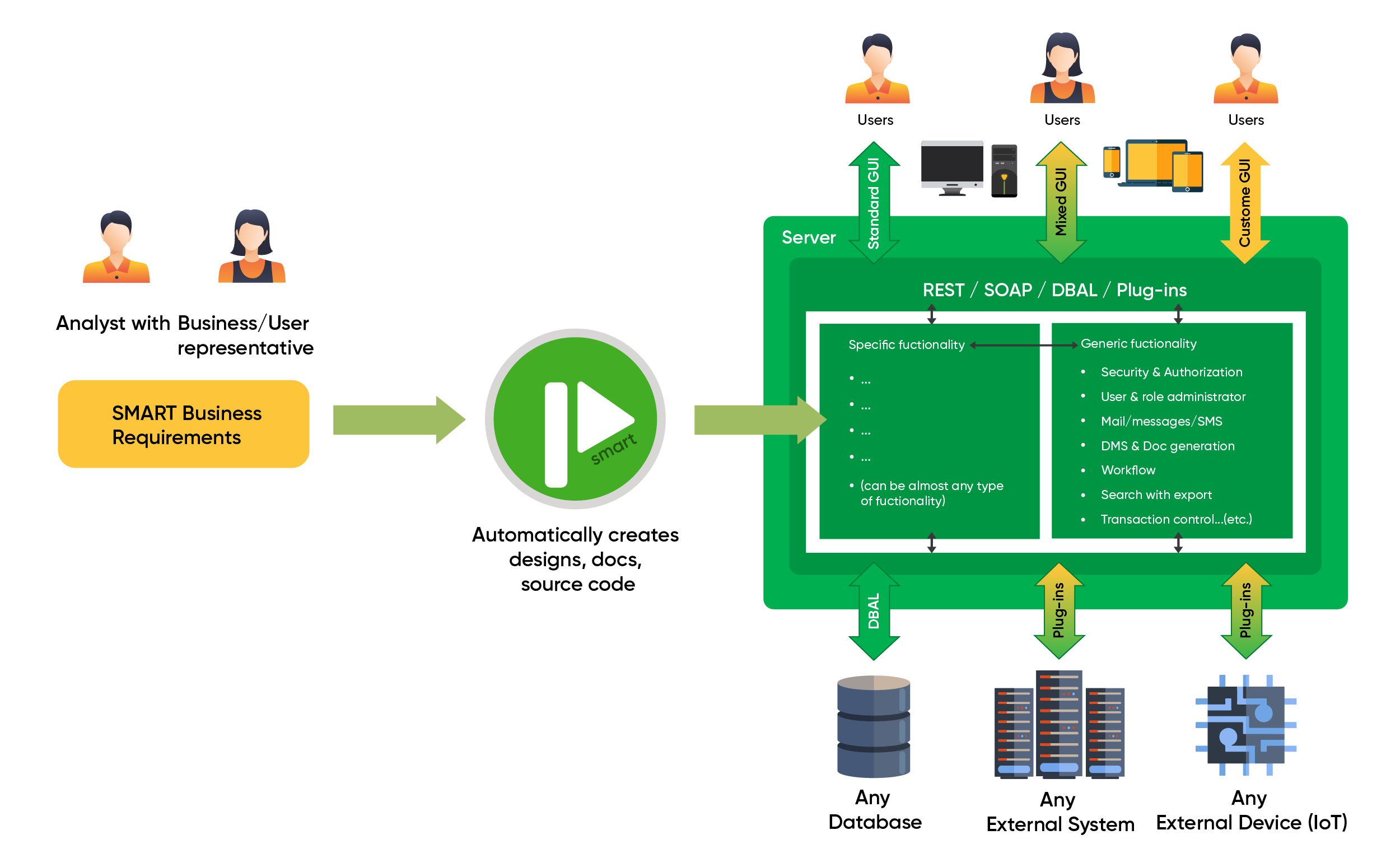
In the diagram below, we see the described system at the top. This diagram uses no symbols or logos and has a limited number of shapes. Unlike the previous diagram, which used no connectors/arrows, this diagram uses arrows as a main component. It is still unclear what purpose the system serves, except that it is some kind of web application.
Source: Wikimedia
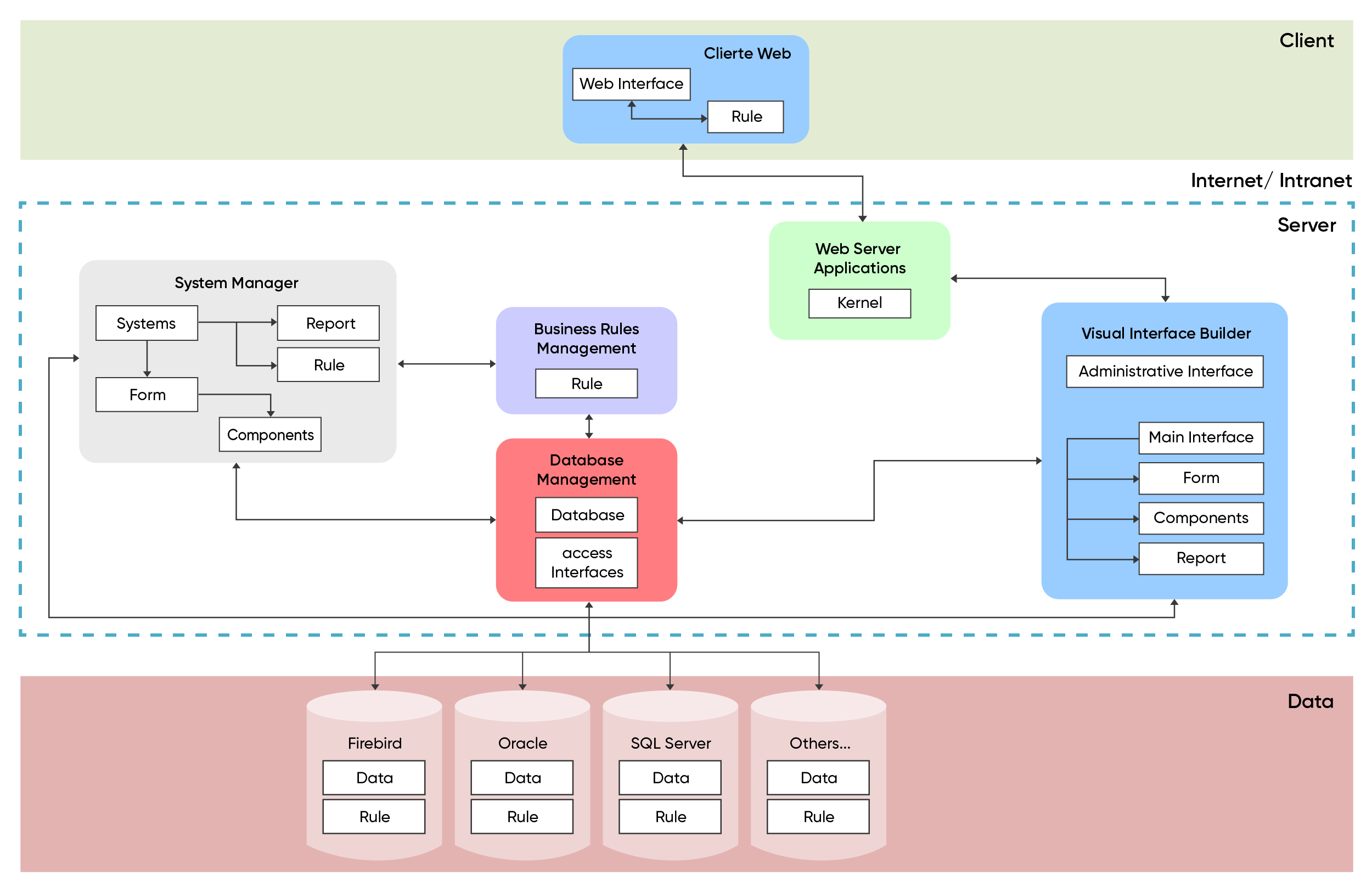
The third diagram is the first that involves actors – we see them as the classical faceless icons. There are symbols, multicolored connectors of two sorts (two- and one-directional). The diagram contains a list of functionalities, describing features of the system. What the system does and who it serves is not explained in this diagram either.
Source: Wikimedia
The three diagrams are very different in visual appeal, what symbols they use and what information they are trying to convey. Indeed, some creativity has gone into making these diagrams. I think there is even a slight chance that we could get "Solution Diagrams" classified as a new artform among the 28 existing art forms listed by Axis, a platform for artists.
Jokes aside, is diagramming supposed to be an artform? Does it require creative skills just to architecture facts in a visual way?
And how useful are these diagrams? Can they be misinterpreted easily? For example, the middle diagram we looked at earlier has arrows in both directions on all connectors – so is there always two-way communication happening between all systems or was that just the default connector used by the diagram’s drawer?
Standardization using the C4 model
At Niteco we have started to look at how we can standardize our diagrams and not only take the artistic requirements out of the drawing but add a long list of benefits that cannot be achieved using traditional methods.
We are starting the standardization process with our Optimizely solutions, and we are using the C4 model. This model allows the drawer to focus on representing the system completely in a visual form, without ambiguity.
C4 comes in three levels, and this post focuses on the first level. Future posts will cover level 2 and level 3.
The first level will be useful across the organization and is also easy to understand for the client. It tells the overall story about the system, its actors, and its integrations.
The C4 diagram below is of a fictious system for the made-up business Automo that owns several car brands. I will not tell you more than that, since the C4 diagram contains all the contextual information within it. Unlike the three diagrams above, the reader should, within minutes, have a good grasp of what this system does and who it serves.
The diagram is almost like a book, where the title and blurb are seen in the blue box in the middle.
Title: Car Parts
Ok, maybe not a fiction best seller :)
Blurb: Car parts websites for all Automo brands that allow mechanics, distributors, staff, and consumers to purchase car parts and accessories for Automo cars.
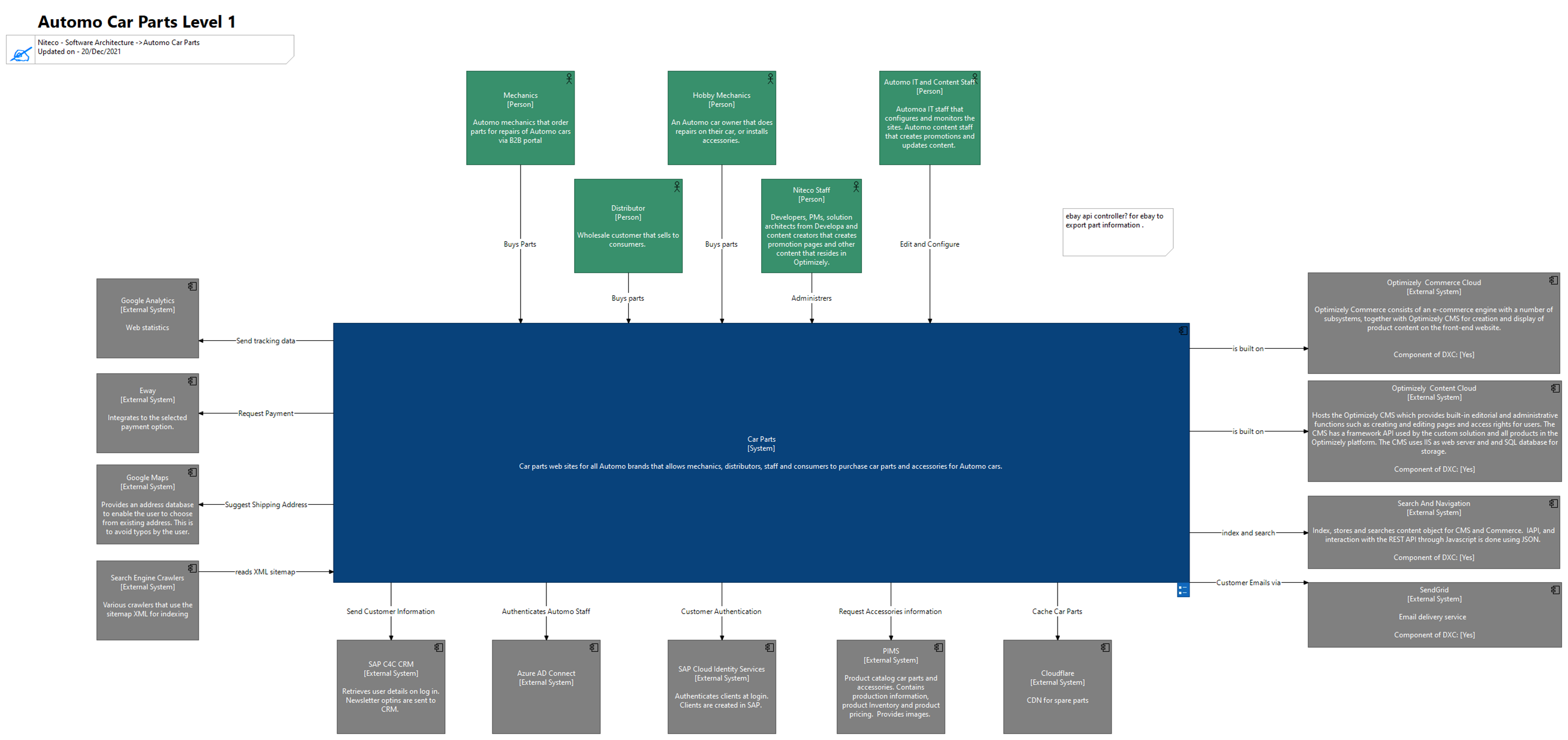
The rest of the "book" is read in whatever order the reader chooses. Each "mini chapter" starts with a box and continues by following a "shooting arrow" to the receiving box, where the chapter ends.
As an example:
Mechanic Buys Parts from Car Parts
Or
Car Parts Request Payments from Ebay.
Or
Car Parts Authenticates Automo Staff via Azure AD Connect.
The Level 1 diagram only contains 3 different types of boxes:
- The blue box represents the described system. This is represented by the Visual Studio solution.
- The grey boxes represent all the external systems with which the described system is integrated.
- The green boxes represent the actors.
There is only one type of connector, the triggering connector. It goes from the actor/system that triggers a system to the triggered system.
Understandable diagrams for all stakeholders
Level 1 of the C4 model does not assume any prior knowledge by the reader. Everyone in the business should be able to read the diagram, without having any knowledge of what a CRM, CMS or PIM is. Automo has a wide variety of business users that range from content writers to IT administrators to E-Commerce marketing staff. Automo often employs new people with no knowledge of the company that quickly need to get up to speed. This diagram is helpful for them as well, since there is an emphasis on providing a good explanation of each system and each actor. At Niteco, the diagram is used by developers, architects, testers, PMs, operations, and sales – our solutions are the centerpiece of what we do, and level 1 gives a one-page visual summary of each solution.
Only the direct integrations are described in C4. The PIMS connects to an ERP system, which would often be included in other architecture diagrams. But Car Parts does not contain a single line of code of integration with the ERP, hence the ERP is not included in the diagram. The C4 diagram displays only what interacts with the described system.
However, to roll out a standardized way of drawing Optimizely solutions at Niteco, C4 rules did not supply enough guidelines. We added our own rules and definitions on top of the ones given by C4.
Optimizely CMS and Commerce are tightly coupled with our code, and we did a lot of thinking on how to describe this in the diagrams. We landed on the solution seen in the diagram above, showing them as external systems.
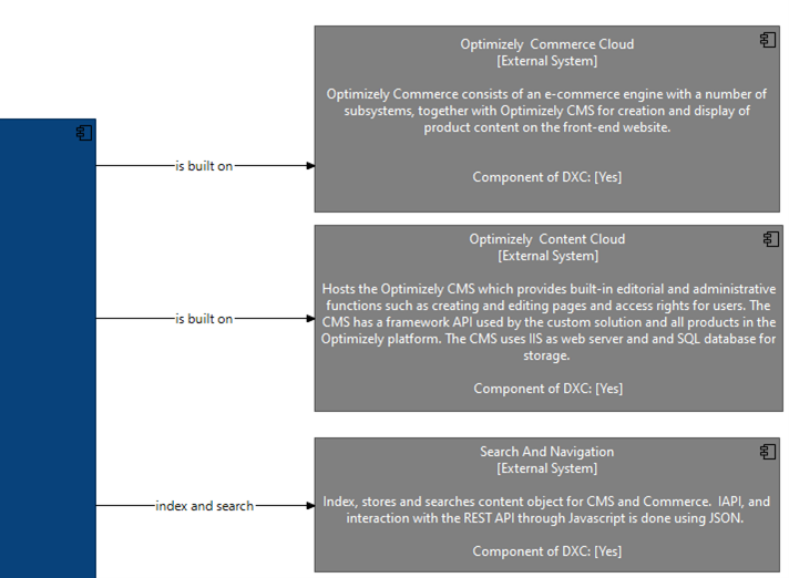 This way, we can quickly see what parts of the Optimizely product suite are included in each solution, and we can also keep track of what version each solution is running by adding them as properties in the model (Component of DXC is an example of such a property).
Using Archimate for diagramming
That leads us to the powerful modelling aspects of Archimate, the tool we are using to draw C4 diagrams.
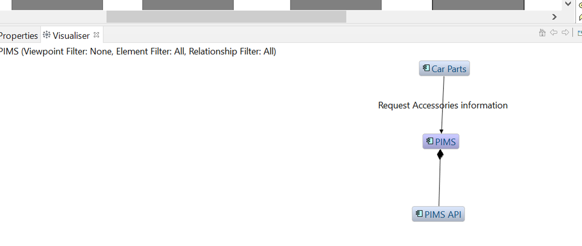
If I select the PIMS box and open the visualizer (see below), I can see all objects that are connected to the PIMS. In addition to Car Parts, the PIMS API (visible in level 2) is connected to the PIMS. In our fabricated example, Niteco is managing more solutions for Automo which also integrate with the same PIMS. As we draw these solutions in Archimate, the visualizer also includes these solutions, even if they are in independent views.
The diagram itself is represented by a view and it presents any aspect of a model. In level 1, we are not showing the PIMS API, but it is still in the model.
When we have modelled all the diagrams for Automo, it is useful to analyze the model whenever we have questions about the enterprise architecture. Automo might be in the process of investing in a new PIMS solution and would like to know all the dependencies on the existing PIMS. By looking at the model, we can quickly find all the connectors to the PIMS and give the client an understanding of the rough costs for replacing their PIMS solution.
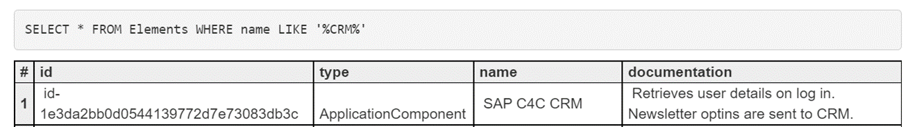
There is also a SQL query language to search the model.
Imagine this scenario: One of Niteco’s sales representatives has a new E-Commerce opportunity where the potential client asks for our experience in integrating to CRM systems. To quickly find out what CRM systems have been integrated in any of our solutions, he can query the model where all diagrams are stored.
Conclusion
That concludes the blog post of the first-level diagramming of the C4 model in Archi for Optimizely Solutions. Many goodies have been included, but this way of drawing diagrams and modelling solutions has even more aspects that I will not be able to cover in one post.
Some of the many benefits of drawing diagrams using the C4 models are:
- Consistency in how solution diagrams are drawn across and within client projects.
- Reaches a wider audience due to the high readability.
- Strict definitions minimize the risk of misinterpreting (remember the double arrows in the second sample diagram?) the diagram.
- Removes the artistic requirements and components in diagramming. No need to think about what colors to apply, what shapes to use, how to connect the shapes, how to position objects, what to represent, what logos to include or what images to decorate with etc. The creative component is eliminated, and all energy can be focused on describing the solution and its integrations.
- Ability to query the model using SQL syntax, providing a tool for sales, architects and developers that quickly need to find information across several systems.